|
◆ MPLS-VPN:PE ⇔ CE間でOSPFを使用:CEルータのコンフィグ設定
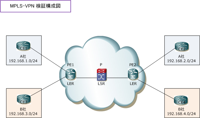
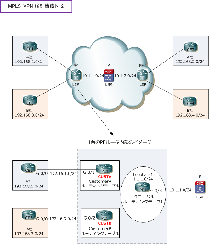
MPLS-VPNにおけるPE ⇔ CE間でOSPFを使用する場合のCiscoコンフィグ設定例(下図)を紹介します。

MPLS-VPNにおけるルータの役割は「Pルータ」「PEルータ」「CEルータ」の大きく3つに分類できます。
先ず、設定が簡単なCEルータの設定例を紹介します。CEルータにMPLSやVRFの設定は必要ありません。
今回の構成ではPE ⇔ CE間でOSPFを使用することから、CEルータではOSPFを設定するだけとなります。
CEルータとPEルータ間のIPアドレスに「 172.16.X.0/24 」を使用しています。End-to-Endの通信には
loopbackアドレスを使用(LAN側アドレスとして使用)します。
◆ MPLS-VPN:CEルータ(CE1、CE2、CE3、CE4)の設定
CE1(config)# interface loopback1
CE1(config-if)#ip address 192.168.1.1 255.255.255.0
CE1(config-if)#ip ospf network point-to-point
CE1(config)# interface GigabitEthernet0/0
CE1(config-if)#ip address 172.16.1.1 255.255.255.0
CE1(config)# router ospf 100
CE1(config-router)#network 192.168.1.1 0.0.0.0 area 1
CE1(config-router)#network 172.16.1.1 0.0.0.0 area 1
|
CE2(config)# interface loopback1
CE2(config-if)#ip address 192.168.2.1 255.255.255.0
CE2(config-if)#ip ospf network point-to-point
CE2(config)# interface GigabitEthernet0/0
CE2(config-if)#ip address 172.16.2.1 255.255.255.0
CE2(config)# router ospf 100
CE2(config-router)#network 192.168.2.1 0.0.0.0 area 1
CE2(config-router)#network 172.16.2.1 0.0.0.0 area 1
|
CE3(config)# interface loopback1
CE3(config-if)#ip address 192.168.3.1 255.255.255.0
CE3(config-if)#ip ospf network point-to-point
CE3(config)# interface GigabitEthernet0/0
CE3(config-if)#ip address 172.16.3.1 255.255.255.0
CE3(config)# router ospf 100
CE3(config-router)#network 192.168.3.1 0.0.0.0 area 1
CE3(config-router)#network 172.16.3.1 0.0.0.0 area 1
|
CE4(config)# interface loopback1
CE4(config-if)#ip address 192.168.4.1 255.255.255.0
CE4(config-if)#ip ospf network point-to-point
CE4(config)# interface GigabitEthernet0/0
CE4(config-if)#ip address 172.16.4.1 255.255.255.0
CE4(config)# router ospf 100
CE4(config-router)#network 192.168.4.1 0.0.0.0 area 1
CE4(config-router)#network 172.16.4.1 0.0.0.0 area 1
|
CEルータの設定上の注意点は以下の2点です。
1. CEに設定するOSPFのプロセス番号は任意
⇒ つまり、PEとCEとで合わせる必要はありません。設定例では適当に「100」とします。
2. PE-CE間で設定するエリア番号は任意
⇒ PE-CE間で使用するエリア番号は、設定例では適当に「1」とします。
◆ MPLS-VPN:PE ⇔ CE間でOSPFを使用:PE1ルータのコンフィグ設定
下図の通り、PE1ルータでは「CE1と接続する設定」と「CE3と接続する設定」と「Pと接続する設定」の
3種類のコンフィグ設定が必要となります。PE ⇔ CE間でスタティックルートを使用する場合と、OSPFを
使用する場合とで異なるコンフィグ部分を太文字にしています。

※ PE1のloopbackアドレス(1.1.1.1)は PE2のloopbackアドレス(2.2.2.2)とMP-BGPピアを確立。
◆ MPLS-VPN:PE1ルータの設定(CustomerA用のVRFとルーティングの設定)
ip vrf CUSTA
rd 1:100
route-target import 10:100
route-target export 10:100
interface GigabitEthernet0/1
ip vrf forwarding CUSTA
ip address 172.16.1.254 255.255.255.0
router ospf 11 vrf CUSTA
network 172.16.1.254 0.0.0.0 area 1
redistribute bgp 65000 subnets
|
◆ MPLS-VPN:PE1ルータの設定(CustomerB用のVRFとルーティングの設定)
ip vrf CUSTB
rd 2:200
route-target import 20:200
route-target export 20:200
interface GigabitEthernet0/2
ip vrf forwarding CUSTB
ip address 172.16.3.254 255.255.255.0
router ospf 12 vrf CUSTB
network 172.16.3.254 0.0.0.0 area 1
redistribute bgp 65000 subnets
|
◆ MPLS-VPN:PE1ルータの設定(グローバルルーティング用のIGP、LDP、MP-BGPの設定)
ip cef
interface loopback1
ip address 1.1.1.1 255.255.255.0
ip ospf network point-to-point
interface GigabitEthernet0/3
ip address 10.1.1.1 255.255.255.0
mpls ip
router bgp 65000
no bgp default ipv4-unicast
neighbor 2.2.2.2 remote-as 65000
neighbor 2.2.2.2 update-source Loopback1
address-family vpnv4
neighbor 2.2.2.2 activate
neighbor 2.2.2.2 send-community both
address-family ipv4 vrf CUSTA
redistribute ospf 11 vrf CUSTA match internal external
address-family ipv4 vrf CUSTB
redistribute ospf 12 vrf CUSTB match internal external
router ospf 1
network 1.1.1.1 0.0.0.0 area 0
network 10.1.1.1 0.0.0.0 area 0
mpls ldp router-id Loopback1
|
以上が「 PE1 」の1台に設定するMPLS-VPN関連のコンフィグとなります。なお、router ospf 1 の設定は
PE-CE間のOSPF設定との関連はなく、MPLS網のグローバルルーティング用のIGPの設定です。
PE-CE間のOSPF設定の注意点として、PEルータでは「Global・CUSTA・CUSTB」でOSPFプロセス番号は
異なる値にする必要があります。また、PE1とPE2とでは左右対称なコンフィグ設定になるよう合わせます。
◆ MPLS-VPN:PE ⇔ CE間でOSPFを使用:Pルータのコンフィグ設定
Pルータでは、ラベルスイッチングが行われるように適切に「IGPとLDP」の設定をすれば良いだけです。
ラベルスイッチングを行いたいインターフェースで「mpls ip」を設定して、「mpls ldp router-id」で
インターフェースを指定するだけです。
Pルータの設定例は以下の通りです。PE1ルータと接続しているインターフェースは「 Gi0/1 」として、
PE2ルータと接続しているインターフェースは「 Gi0/2 」とします。Pルータの router ospf 1 の設定は
PE-CE間のOSPF設定との関連はなく、MPLS網のグローバルルーティング用のIGPの設定です。
◆ MPLS-VPN:Pルータの設定
ip cef
interface loopback1
ip address 3.3.3.3 255.255.255.0
ip ospf network point-to-point
interface GigabitEthernet0/1
ip address 10.1.1.254 255.255.255.0
mpls ip
interface GigabitEthernet0/2
ip address 10.1.2.254 255.255.255.0
mpls ip
router ospf 1
network 3.3.3.3 0.0.0.0 area 0
network 10.1.1.254 0.0.0.0 area 0
network 10.1.2.254 0.0.0.0 area 0
mpls ldp router-id Loopback1
|
◆ MPLS-VPN:PE ⇔ CE間でOSPFを使用:PE2ルータのコンフィグ設定
最後にPE2ルータの設定をします。PE1ルータ同様にコンフィグ設定は論理ルータごとに考えていきます。
PE ⇔ CE間でスタティックルートを使用する場合と、OSPFを使用する場合とで異なるコンフィグ部分を
太文字にしています。

◆ MPLS-VPN:PE2ルータの設定(CustomerA用のVRFとルーティングの設定)
ip vrf CUSTA
rd 1:100
route-target import 10:100
route-target export 10:100
interface GigabitEthernet0/1
ip vrf forwarding CUSTA
ip address 172.16.2.254 255.255.255.0
router ospf 11 vrf CUSTA
network 172.16.2.254 0.0.0.0 area 1
redistribute bgp 65000 subnets
|
◆ MPLS-VPN:PE2ルータの設定(CustomerB用のVRFとルーティングの設定)
ip vrf CUSTB
rd 2:200
route-target import 20:200
route-target export 20:200
interface GigabitEthernet0/2
ip vrf forwarding CUSTB
ip address 172.16.4.254 255.255.255.0
router ospf 12 vrf CUSTB
network 172.16.4.254 0.0.0.0 area 1
redistribute bgp 65000 subnets
|
◆ MPLS-VPN:PE2ルータの設定(グローバルルーティング用のIGP、LDP、MP-BGPの設定)
ip cef
interface loopback1
ip address 2.2.2.2 255.255.255.0
ip ospf network point-to-point
interface GigabitEthernet0/3
ip address 10.1.2.1 255.255.255.0
mpls ip
router bgp 65000
no bgp default ipv4-unicast
neighbor 1.1.1.1 remote-as 65000
neighbor 1.1.1.1 update-source Loopback1
address-family vpnv4
neighbor 1.1.1.1 activate
neighbor 1.1.1.1 send-community both
address-family ipv4 vrf CUSTA
redistribute ospf 11 vrf CUSTA match internal external
address-family ipv4 vrf CUSTB
redistribute ospf 12 vrf CUSTB match internal external
router ospf 1
network 2.2.2.2 0.0.0.0 area 0
network 10.1.2.1 0.0.0.0 area 0
mpls ldp router-id Loopback1
|
◆ MPLS-VPN:PEルータのステータス確認コマンド
MPLS-VPNではPEルータでのステータス、ルーティング確認が重要となってきます。今回はPE1ルータの
ステータス確認コマンドを紹介しますが、同様の考え方で、PE2ルータのルーティングも確認しましょう。
◆ PE1# show ip route vrf CUSTA
⇒ MP-BGPにより「192.168.2.0/24」のBGPルートを受信していることを確認。
◆ PE1# show ip route vrf CUSTB
⇒ MP-BGPにより「192.168.4.0/24」のBGPルートを受信していることを確認。
◆ PE1# show ip cef vrf CUSTA 192.168.2.0
⇒ ラベルが2つ付いていることを確認。
◆ PE1# show ip cef vrf CUSTB 192.168.4.0
⇒ ラベルが2つ付いていることを確認。
◆ PE1# show ip bgp vpnv4 all
⇒ MP-BGPで通知された「Next Hop」は、MP-BGPピアのアドレスであることを確認。
◆ PE1# show ip bgp vpnv4 all 192.168.2.0
⇒ Extended Communityに「RT:10:100」が付加されていることを確認。
⇒ リモートのラベル(out)が付加されていることを確認。
◆ PE1# show ip route
⇒ 常にMPLS-VPN網内のルーティング情報だけがルーティングテーブルに存在することを確認。
|


